Capital expenditure in processing equipment must be justified by clear operational returns. When evaluating industrial ultrasonic sieving equipment, the return on investment (ROI) is primarily driven by uptime preservation and yield improvement, particularly when handling problematic materials.
The Cost of Inefficient Sieving
Materials with strong adsorption, high static electricity, or extreme fineness naturally resist standard mechanical separation. The hidden costs here are substantial:
Labor Costs: Manual screen cleaning is highly labor-intensive.
Consumables: Aggressive physical cleaning wears out the screen mesh cloth faster, increasing replacement frequency.
Product Loss: Poor screening efficiency means good product is often rejected alongside oversized waste.
The Ultrasonic Economic Advantage
Integrating an ultrasonic power supply and transducer directly addresses these profit leaks.
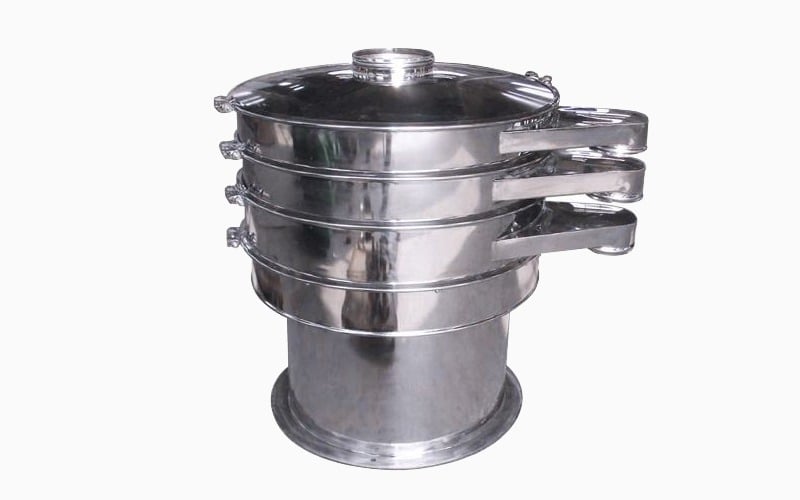
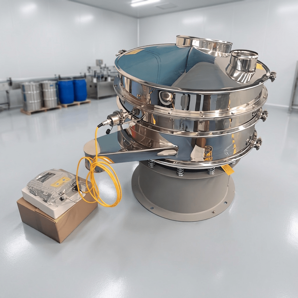
Sustained Throughput: By continuously breaking down material agglomeration and preventing static buildup, the machine maintains peak throughput. A standard S49U10-B model (950mm diameter, 0.8kw power) runs continuously without the throughput degradation seen in non-ultrasonic models.
Quality Control: Maintaining exact aperture sizes guarantees product consistency. The ultrasonic waves clean the net rapidly and efficiently without deforming the mesh.
Energy Efficiency: The localized application of ultrasonic energy to the mesh requires significantly less overall power than upsizing a standard vibration motor to force heavy, sticky materials through a screen.
For factories processing high-value fine powders, the reduction in downtime alone typically offsets the initial equipment investment within the first few quarters of operation.